How COSMIC Satellites See the Atmosphere
Goal
Engage students with a demonstration of bending light rays.
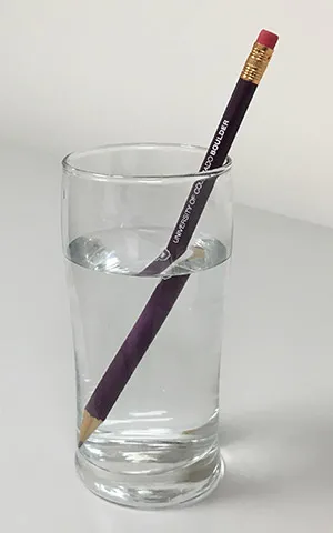
Begin the lesson with a physical demonstration of light bending as it passes between air and water to spark students' curiosity with a very tangible example.
Later in this lesson sequence students will use a computer-based simulation to explore details of the phenomenon of refraction. Before students encounter the computer simulation, it is important for them to observe refraction with their own eyes "in the real world." After seeing a physical demonstration, students wiil be more prone to accept the results of the computer-based simulations as being accurate models of physical events. Also, demonstrations of actual physical phenomena can be more memorable for many students than something viewed on a screen.
The Introduction: Physical Demonstration of Refraction section of our Measuring Density by Bending Light activity, provides three options.
- The best option for a memorable and compelling demonstration is Option 3: Tub of Water Bends Laser Beam. This option does, however, take the most time and requires more supplies than the other two possibilities.
- The simplest and quickest demonstration is Option 1: Straight Object Appears Bent in a Glass of Water.
- An intermediate option, in terms of time required and equipment needed, is Option 2: Beam of Light Bends as it Passes Through Glass or Water.
Explore the relationship between density and bending light rays with a computer simulation.
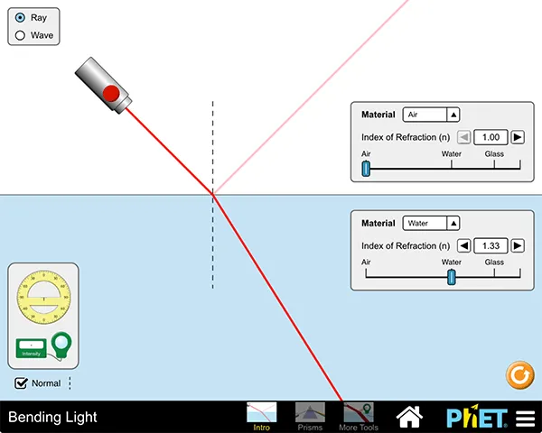
Students explore refraction in more depth using a computer-based simulation. The simulation allows students to quickly switch between substances that light passes through, helping them discover how light refracts by different amounts depending on the index of refraction and density of the substance. Students will determine the relative density and index of refraction of three unknown samples by conducting "virtual experiments" within the computer simulation.
- Tell students to complete the Computer Simulation of Simple Refraction in the Measuring Density by Bending Light activity.
- After completing their work with the computer simulation have students watch this short video that explains refraction and describes Snell's Law, the concept from physics that explains the mathematics of refraction. (Note: the full video is 7 minutes long and requires registration to view; however, the key points needed for this activity are contained in the first 2:20 of the video, which does not require registration to see.)
Explain how the bending of radio waves allows meteorologists to measure the atmosphere.
Students read about and compare two types of electromagnetic radiation, visible light and radio waves and about the layers of Earth's atmosphere. Finally, they view a video about the COSMIC satellites and radio occultation.(See list of readings and video below.)
Students may need help with some of the steps in the logic of how the radio occultation technique provides scientists with data about temperature, pressure, and humidity at different heights in the atmosphere. See Radio Occultation Background (below) for a more detailed explanation of the technique and its use for measuring aspects of the atmosphere.
Student Readings and Video mentioned above:
- About Electromagnetic (EM) Radiation: Compare Visible Light with Radio Waves
- About the Layers of Earth's Atmosphere
- Video - Satellite Signals from Space: Smart Science for Understanding Weather and Climate
After reading about electromagnetic radiation, ask students to make a prediction, based on a comparison between red and blue light, about how the bending of radio waves might compare with the bending of visible light. Red light has a longer wavelength than blue light, and red light bends less than blue light. Since radio waves have much, much longer wavelengths than visible light (either red or blue), it is reasonable to expect that radio waves bend less than rays of visible light of any color.
Elaborate by having students interpret data from COSMIC that shows atmosphere layers.
- Students will interpret a plot of temperature vs. altitude data that was generated by the COSMIC satellite using the radio occultation technique.
- Show students the graph below of temperature vs. altitude data. Tell them it was created from data from the COSMIC satellite using the radio occultation technique. Ask them to identify the altitude of the tropopause, the boundary between the troposphere and the stratosphere, and to explain their reasoning.
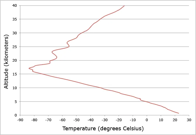
The tropopause is at an altitude of about 17 kilometers in this graph. Below 17 km, in the troposphere, temperatures decrease with altitude. Above 17 km, in the stratosphere, temperatures increase with altitude.
Evaluate students' ability to transfer knowledge of refraction to different situations.

Lead students in a discussion of situations in which it is useful to be able to infer the traits of some material or object from afar without directly touching it with any sort of measurement system. Examples include satellite remote sensing, use of infrared thermometers to measure the temperature of a lava flow, and the use of telescopes and spectrometers to study distant stars or planets.
Ask students to explain how the bending of light tells them something about the air in each of the following situations:
- when the Sun looks like a squished oval instead of a circle at sunset or sunrise
- when the pavement in the distance appears to shimmer and looks like a silvery puddle of water on a hot summer day
- when stars twinkle at night
See the Part 1 Rubric for examples of student answers at different levels of proficiency.
Radio Occultation Background
In the activities above, students read about and compare two types of electromagnetic radiation, visible light and radio waves. They also read about the layers of Earth's atmosphere. Finally, they view a video about the COSMIC satellites and radio occultation, and explain how the bending of radio waves beamed between satellites allows scientists to measure traits of the atmosphere.
Students may need help with some of the steps in the logic of how the radio occultation technique provides scientists with data about temperature, pressure, and humidity at different heights in the atmosphere. Specifically:
- We can observe how light rays bend when light passes from a substance with one index of refraction into another substance with a different index of refraction.
- The density of a substance and its index of refraction are often (but not always!) related. In general, higher density and higher index of refraction go together.
- Exceptions to this trend include olive oil and alcohol as compared to water. Water has a higher density than either alcohol or olive oil, however both alcohol and olive oil have a higher index of refraction than water.
- Radio waves, like light, bend when they pass between substances of different densities.
- If radio waves beamed from one satellite to another pass through the atmosphere, they bend. The amount of bending depends on the density of the portions of the atmosphere the radio waves pass through.
- The density of the atmosphere at a specific place depends on a combination of air temperature, air pressure, and humidity... therefore each of these factors influences how much radio waves bend.
- The temperature, pressure, and humidity of the atmosphere vary with altitude. In fact, they vary so much that scientists use different names for layers of the atmosphere based on the characteristics of the atmosphere at each height. Therefore, the radio occultation technique allows us to observe different layers of the atmosphere by measuring the amount of bending of radio waves as they pass through air with varying density.
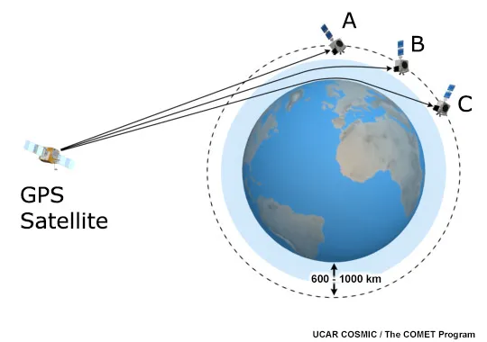
The diagram below illustrates how radio occultation is used to measure properties of the atmosphere at different heights. Have students explain the features of this diagram and the science behind radio occultation based on their knowledge of refraction of electromagnetic waves as they pass through media of different densities, the vertical structure and layers of Earth's atmosphere, and the similarities and differences between visible light and radio waves.
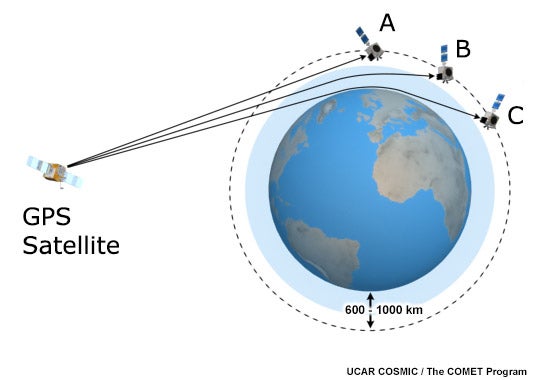
This diagram shows how radio waves beamed from one satellite to another bend when the radio waves pass through Earth's atmosphere. The radio waves are beamed from the GPS Satellite in the higher orbit to the COSMIC satellite in the lower orbit at positions A, B and C.
- The signal from the GPS satellite to position A does NOT pass through Earth's atmosphere at all. Therefore, the radio waves DO NOT bend and simply move in a straight line between the two satellites.
- The signal from the GPS satellite to position B passes through the upper portions of Earth's atmosphere. The radio signal is bent a little bit as is passes through the upper atmosphere. The values of air pressure and density at high altitudes in the atmosphere are very small. Therefore, the index of refraction of the air at high altitudes is small, so the radio waves bend only slightly.
- The signal from the GPS satellite to position C passes through both the upper AND lower portions of Earth's atmosphere. The radio signal bends the most as it passes through the lower atmosphere. The values of air pressure and density at low altitudes in the atmosphere are much greater than they are at high altitudes. Therefore, the index of refraction of the air at low altitudes is larger, so the radio waves bend the most when they pass through the relatively dense air that is nearer to ground level.
Grade Level
- Middle School
Educational Standards
Next Generation Science Standards
- SEP: Developing and Using Models; Analyzing and Interpreting Data; Constructing Evidence
- DCI: MS- PS4.B: Electromagnetic Radiation
- CC: Cause and Effect, Patterns